Sorry no pictures of the actual scope but got a lot done over the Xmas holidays, all the major components are complete, just need to debug.
I had an epiphany when I was thinking about the back plate for the mirror box – I had a 15lb barbell hanging off the back of the scope but the back plate was 1/4″ plywood so not strong enough long term. I was noodling both how to route power to the scope without too much insightly wiring and how to add wieght to the back when I realized I could kill two birds with one stone – off to Amazon, ordered a 15 lb 12v 20Ah scooter battery for $70 that should run the scope all night and then some, plus make it completely self contained. The scope now balances beautifully with a Coma Corrector and ES 2″ 18mm eyepiece, perhaps a tad back heavy.
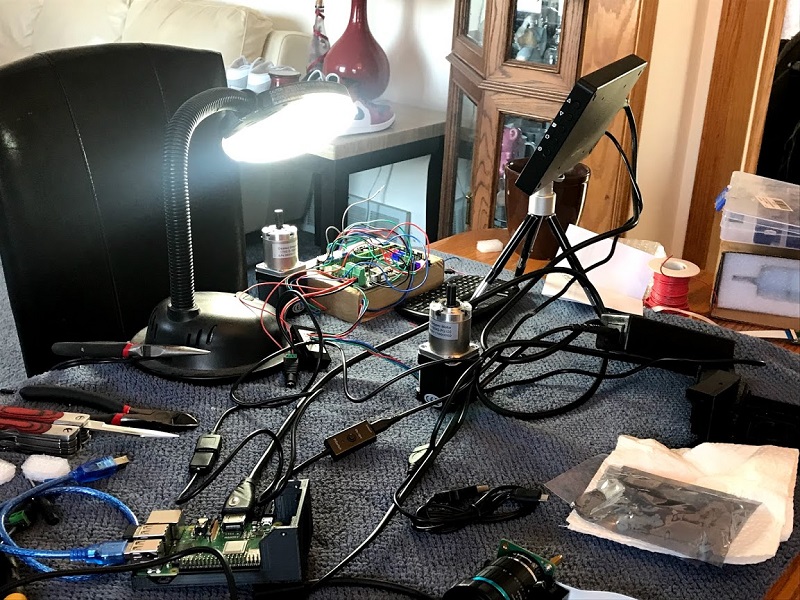
I completed the controller/plate solver setup and mounted it on the scope, just need to run wiring for power and route HDMI, power, and USB to the touchscreen thats mounted on a pole on the rocker box. Here’s everything set up on the bench, wiring the MKS board for TMC 2130 motor drivers, some extra jumpers are required to allow the software to control the motors via the SPI bus.
I tested the motors and MKS GEN-L 1.0 controller with the OnStep software and quickly realized my controller is VERY underpowered to run my 100:1 ratio 200 steps per revolution motors at a reasonable slew rate. For the time being I am installing some 400 steps per rev motors with the MKS board – slow still but good enough for testing the mechanical side. I need a faster processor, so I ordered a Teensy 4.0 and will build a simple circuit on a breadboard to run the motors for the time being, I have the PCB to build a more elaborate controller once everything is up and running. The Teensy 4.0 is 667kHz step rate versus the 13kHz supported by the Mega2560 in the MKS board.


A 12v to USB converter works great to run the Rpi 3B+ controller/plate solver. It’s connected via HDMI/USB to 7″ touchscreen (runs on 12v) with a wireless keyboard/mouse. I ended up using a Raspberry Pi HQ camera in the controller rather than the v2.1 that the case etc. was designed for as it was meant for a C mount lens and I have a CS, and the adapters weren’t right. No biggy, I was going to use the HQ for a allskycam but I have one based on a ASI224MC so not very high on the project queue. Next step is mount the motors, add an axle for the altitude bearing and attach it to the motor via a belt, and add a belt to the azimuth bearing. More info / pics next post.
Scope is all set up and ready to observe with unpowered – I built a dolly with casters to put the scope on as moving it around the garage fully assembled is not much fun and taking the trusses on and off every session is a bit of a disincentive to get short build sessions in. The new truss attachments are working well enough but are fragile – the laminated 1/4″ plywood tends to pop off so they had to be screwed on. Probably needs a solid wood or ABS design but that can wait. I have a pair of wheelbarrow handles roughed in with 2x4s that need to be shaped a bit and painted with longer bolts with nice handles made. But the 2x4s with a couple of holes in them are functional